

Introduction
In this section we will first look at some of the methods of hazard identification that were briefly mentioned in the session “Hazards: definition, characterisation and identification techniques”, namely Fault Tree Analysis (FTA), Failure Mode Effects Analysis (FMEA) and Failure Modes and Effects Criticality Analysis (FMECA). These methods are extremely commonplace, particularly in high hazard industries, and in many ways represent both industry standard and best practice and as such require more in-depth study during this course.
From there we will look deeper into fault studies and consequence assessment and what they mean in the context of certain high hazard industries such as the nuclear industry.
By the end of the session you will be able to:
- Analyse the applicability of failure analysis to prediction of future failures
- Evaluate FTA, FMEA, FMECA and the strengths and weaknesses
- Evaluate the application of fault studies and consequence assessment
- Apply this evaluation to the synthesis of FMECA tables and FTA diagrams

Failure Analysis
Failure analysis is a process that takes place following some form of failure. Given this definition, then arguably fault finding prior to carrying out a repair could be considered the very simplest form of failure analysis.
This is a little extreme though, and generally failure analysis can be considered to be the process of collecting and analysing data after a failure to determine the causes of the failure, both proximal and ultimate. Once the cause has been discovered, corrective actions can be designed to prevent the failure from happening again. It is this step that really feeds into the writing of safety cases, as knowledge gained from failures in other plants or other similar situations is often the basis for effective design of systems.
If a machine or plant fails there is usually a chain reaction of cause and effect, very rarely is it found that a single event has led to the failure. Analysis of this chain has a two-fold benefit, first breaking the chain at any stage should prevent the failure from occurring downstream, secondly prior symptoms can be used as warning of impending failure, allowing an intervention to be made to prevent the failure from happening. Both of these things can be included in a safety case to argue as to why the new method of carrying out a task will prevent known previous failures from occurring again.
If done correctly, and acted on properly, failure analysis is a worthwhile process from every angle, saving lives, money and resources. A wide variety of methods can be used in failure analysis, both technical and non-technical. Technical includes such things as microscopy, None-Destructive Testing (NDT) methods such as CT (Computer Tomography) scanning and spectroscopy. Non-technical methods would include things such as interviewing operators and engineers to discover if any non-normal situations had been noticed before the failure took place.
The following video from the National Aerospace Laboratory (NLR) in the Netherlands shows the depths to which it can be necessary to take failure analysis, but also the potential benefits.
To take the incident in the video as inspiration this could be directly translated into a simple entry into a safety case – for example “oil mount suspension are safe as they are fixed to the structure with bolts that have the same thermal expansion properties, namely the bolts are of nickel alloy as is the plate, evidence of this being a safe approach is provided by the NLR investigation into the 2001 F-16 crash”.
Failure Analysis Case Study – Failed Shear Key Rods on the Bay Bridge
As an in depth understanding of failure analysis lies outside the scope of this course a look at each of the possible stages, or possible methods of carrying out analysis, is not included. However, a brief case study is presented as a useful example of the way in which a failure analysis could be carried out.
In 2013 two shear key rods on the San Francisco Bay Bridge were found to have failed. This led to the closure of the bridge, never an act that a public body carries out lightly. Failure analysis was carried out and is outlined here – a link to the full analysis is provided at the end for interest.

Steps
Visual observation
As would probably be assumed the first step was to simply look at the failed bolts. This is the first step in all failure analysis. In this case signs of brittleness were revealed with no evidence of plastic deformation before the failure. There was evidence of cracking which was the final breaking point. The engineers carrying out the analysis suspected hydrogen was involved in the production of the cracks.
Scanning Electron Microscopy
SEM was carried out to gain a better understanding of the fracture mechanism. It was found full fracture occurred once the strength of the rod was no longer able to support the load due to the cracking.
Micro-structural Examination
Cross-sections were examined to reveal more about the microcrystalline structure of the material and the interworking bonds.
Hardness testing
Two methods were used, namely Rockwell C and Knoop Microhardness. This revealed that heat treatment had not been carried out properly.
Tensile testing.
Yield, tensile and elongation were all found to meet the requirements.
Charpy V-Notch Impact Test
Was used to show toughness, which was found to be low.
Chemical analysis
This was the final test and should that the steel met requirements.
Conclusion
It was found that the rods failed due to hydrogen embrittlement. The rods were susceptible to hydrogen embrittlement due to the high tensile load and hydrogen already in the material. The rods met the design requirements, however because they were of a material that was not homogenous there were different strengths in different areas and toughness was low.
Again, carrying out analysis to this level will mean that whilst the failure on the Bay Bridge has already occurred, the same failure should not happen again in the same circumstances.
The full fracture analysis report is available from baybridgeinfo.org if interested but it does not need to be read for this course.
Fault Studies
Fault studies is a term that can subtly different meanings in different industries, but for the purposes of this course we will use the following definition, which forms part of a larger definition given by the Office of Nuclear Regulation:
“…Fault Studies is the application of design basis, probabilistic safety and severe accident analysis techniques…” (ONR, 2017)
Taking this as our starting point, we will now look at three commonly used techniques, namely Fault Tree Analysis (FTA), Failure Modes Effects Analysis (FMEA) and Failure Modes and Effects Criticality Analysis (FMECA).
Fault Tree Analysis (FTA)
Fault tree analysis is a method that uses Boolean logic to combine a series of lower level events to deductively conclude the root to some undesired state – usually failure. It is used extensively in the safety and reliability engineering fields to gain an understanding of how systems fail, and from there identify the best ways to reduce risk. It is also used to give an idea of event rates of a safety accident or functional failure – that is a failure on a global level not a local one (the plant has to be shut down, not the number 3 furnace is out of commission for example). It is common in high hazard industries such as aerospace or the chemical industry, but it can also be found in fields as diverse from engineering as social services. It is also commonly used in software engineering for debugging.
Fault tree analysis can be used in a variety of ways:
- understand the process that has led to the top-level event (failure)
- show compliance with the (input) system safety / reliability requirements.
- prioritise the contributors leading to the top event i.e. pointing out which of the lower level events is the most important – for example if a top level failure can be reached in 3 ways, but the same intermediate step occurs in all three of them that should be one of the first areas to have resource dedicated to it
- monitor and control the safety performance of the overall system – for example is it safe to fly this aircraft with fuel valve x inoperative? If it is safe, how long will it remain safe?
- assist in designing a system. The FTA can be used as a design tool that helps to create (output / lower level) requirements.
- help with the creation of diagnostic manuals / processes.
Of particular interest are the 3rd and 4th points from a safety case point of view. If it can be shown that all possible routes to failure have been mitigated, and that even with a specific local failure there is not a global failure, then the safety case is strong in that regard.
The process for developing a fault tree is explained in the following video, which also explains how they can be used to improve reliability and to make best use of available resource:
Failure Modes Effect Analysis (FMEA)
FMEA is the process of reviewing components, assemblies and systems to identify possible ways in which they may fail, and what the effect of that failure might be. As a general rule, for each component an FMEA worksheet is generated showing all possible failure modes, along with the effect on the system. These worksheets can then be combined to give a worksheet for the assembly, and in turn a worksheet for the entire system, alternatively the assemblies and system can be reviewed independently and have their worksheets generated separately. Reliability and failure engineering professionals generally consider the most robust approach is to use a combination of both methods – that is worksheets from the lower levels are used to generate a higher level worksheet, and then the higher level is reviewed as an independent item as well.
Unlike FTA FMEA is a form of inductive process – that is the component is considered the start point and the failure the end point, as opposed to the other way around, making FMEA a form of forward logic. In addition, it can be a purely qualitative process, though it is more commonly combined with failure rate models and a statistical failure mode ratio database to turn it into a quantitative system.
There are a variety of FMEA templates available, all with their own strengths and weaknesses, and whilst it is commonplace for there to be a company standard template if the professional carrying out the analysis feels another template is better suited then they should be arguing for its use.
What an FMEA does is explained in the following video from Quality One, an American reliability engineering firm:
Whilst we now have an idea of what an FMEA does, we also need an understanding of what it is, why we do it, when we do it and perhaps most importantly how we do it. We will briefly look at each of these in turn now.
What is FMEA
FMEA is a structured approach to discovering potential failures. Failure Modes are the ways in which a process can fail, and effects are the ways that these failures lead to waste, defects or other harmful outcomes. The intention of FMEA is to identify these modes, prioritise them and limit them or their effects, or ideally remove them altogether. There are two broad categories of FMEA, Design FMEA (DFMEA) and Process FMEA (PFMEA).
They are examined in the two videos:
Why perform FMEA
Put simply, the sooner a failure is discovered, the less it will cost. The recent troubles with the Boeing 737 Max are a prime example. Had the issue with the MACS system been discovered early in the design and production cycle the cost would have been minimal – it is probable the system could simply not have been included in the aircraft. As it was, the cost to Boeing as of October 2019 was in excess of $9BN (Frost, 2019).
FMEA is one of a range of tools that can be used to discover failure as soon as possible. As such its benefits include:
- Highlights choices for mitigating the risk
- Higher capability of verification and validation of changes
- Product and Process collaboration
- Lower cost solutions
- Utilisation of standard work and tribal knowledge
When to Perform FMEA
There are no hard and fast rules as to when FMEA should be performed, however there are times when it makes sense. These include:
- When designing something new – be it product, process or service
- When overhauling or upgrading something already in existence
- As part of a quality improvement goal
- As a method of understanding why a process or product is failing
In addition, however as quality is an ongoing process FMEA should be performed occasionally throughout the lifecycle of a process or product to ensure that it remains up to date.
How to Perform FMEA
Whilst there are variations in how each company performs FMEA internally, there are 7 steps which remain constant. The steps are separated so that the size of the team involved is correct – there is no point having a member present for a step that does no concern them, and it can lead to resentment which reduces the overall effectivity of the process.
The seven steps are:
- Carry out pre-work and assemble the team
- Path 1 Development (Requirements through severity ranking)
- Path 2 development (potential causes and controls through occurrence ranking)
- Path 3 Development (Testing and Detection Controls through Detection Ranking)
- Prioritisation, action planning and task assignment
- Actions taken and design review
- Re-ranking of RPN and closure
How to carry out a PFMEA is discussed in the following video:
Whilst this is based on a Process FMEA, the methodology for carrying out a Design FMEA is extremely similar.
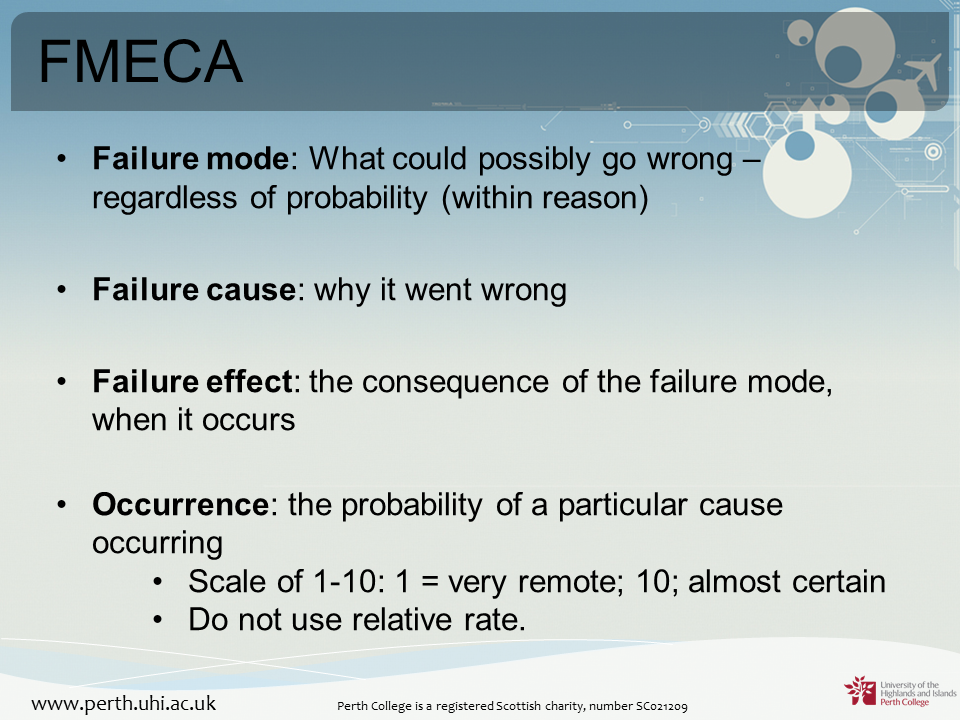
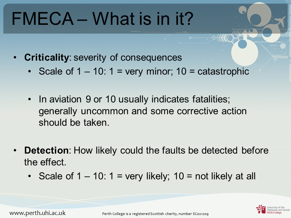
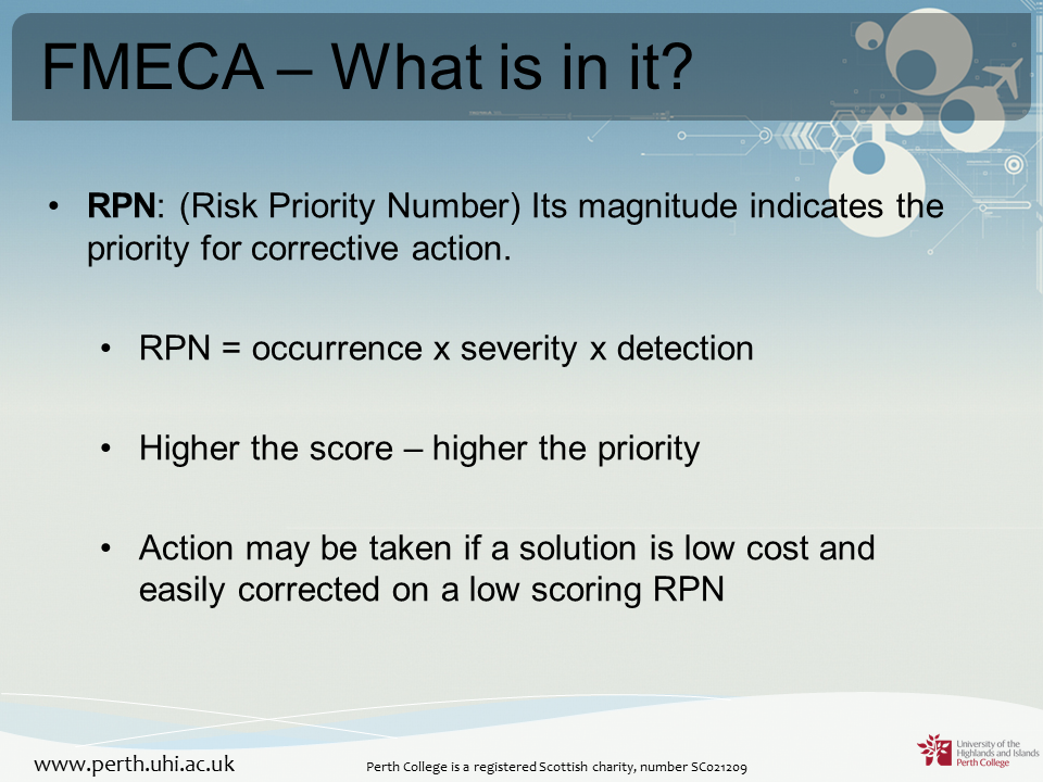
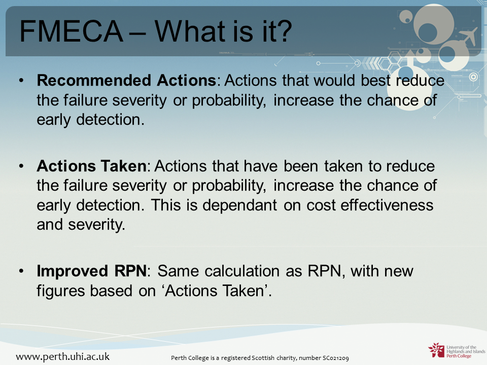
Failure Modes and Effects Criticality Analysis (FMECA)
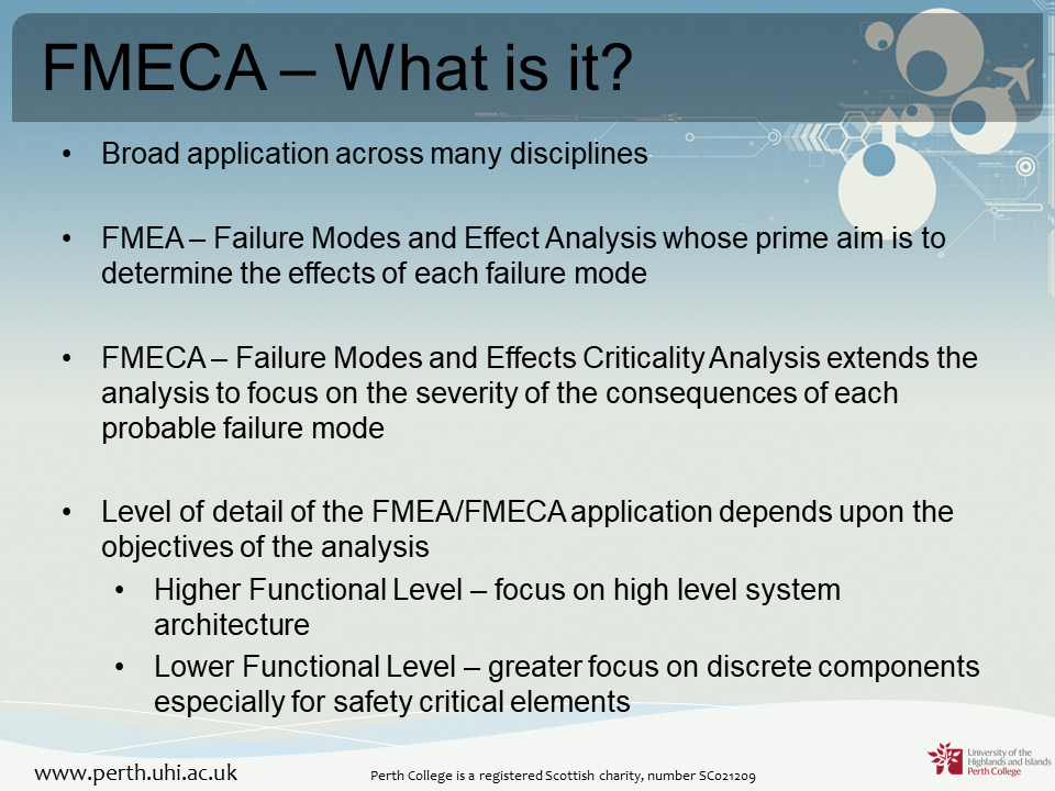
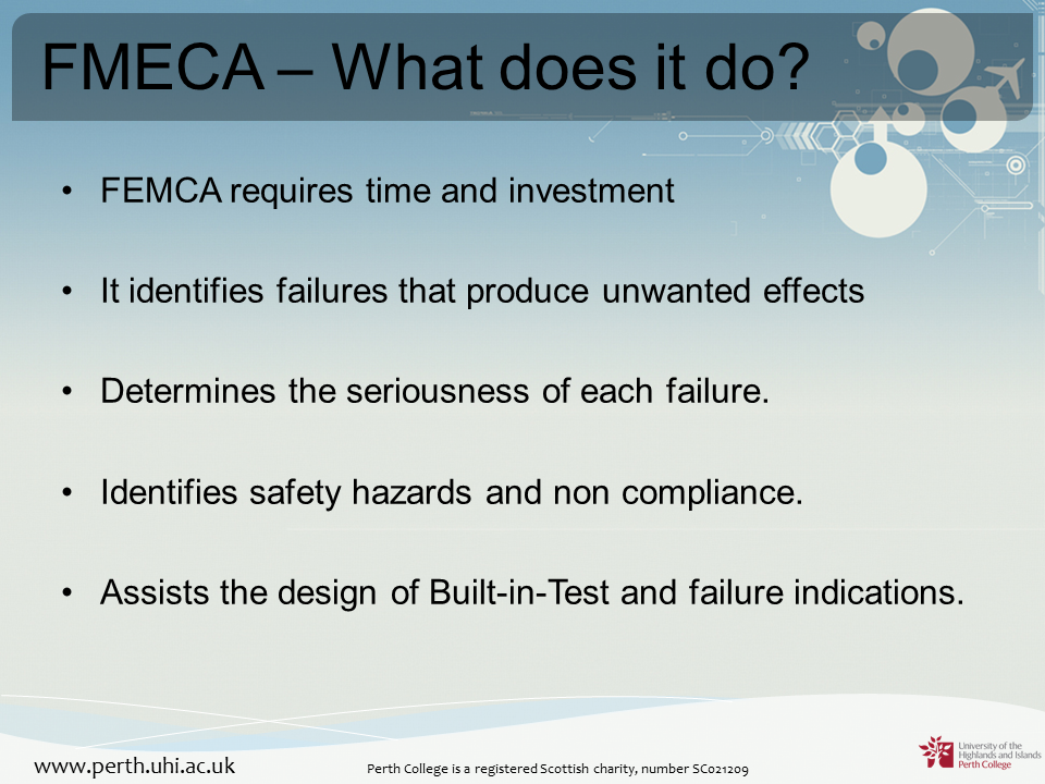
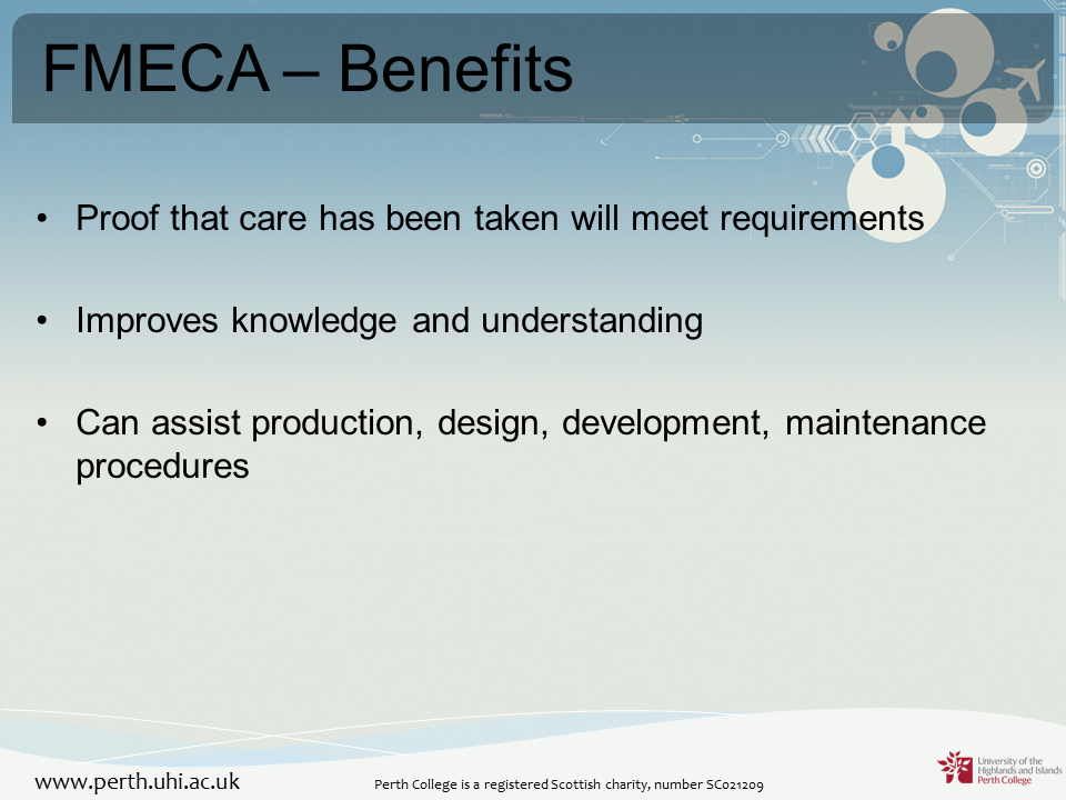
FMECA is an extension of FMEA that extends the analysis to focus on the severity of the consequence of each probable failure mode.
FMECA is examined in the following video:
And in further detail in the following PowerPoint from Calum Aird at Perth College UHI:
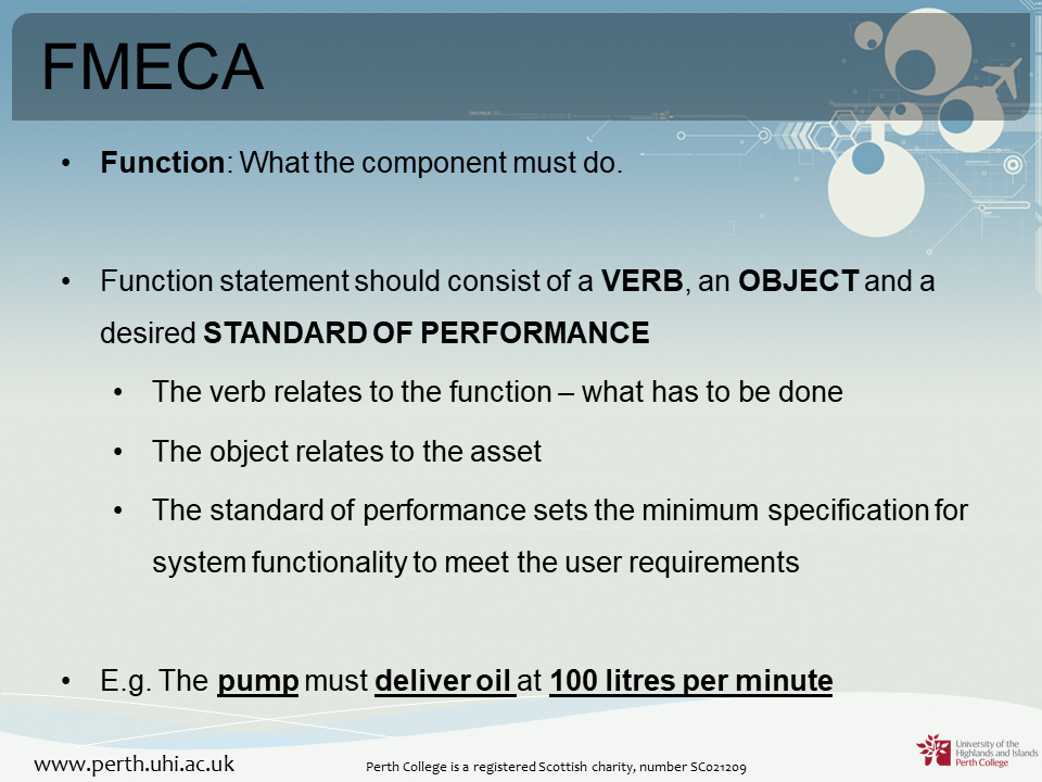
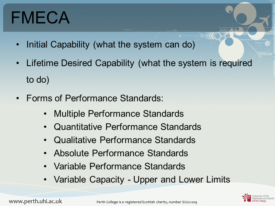
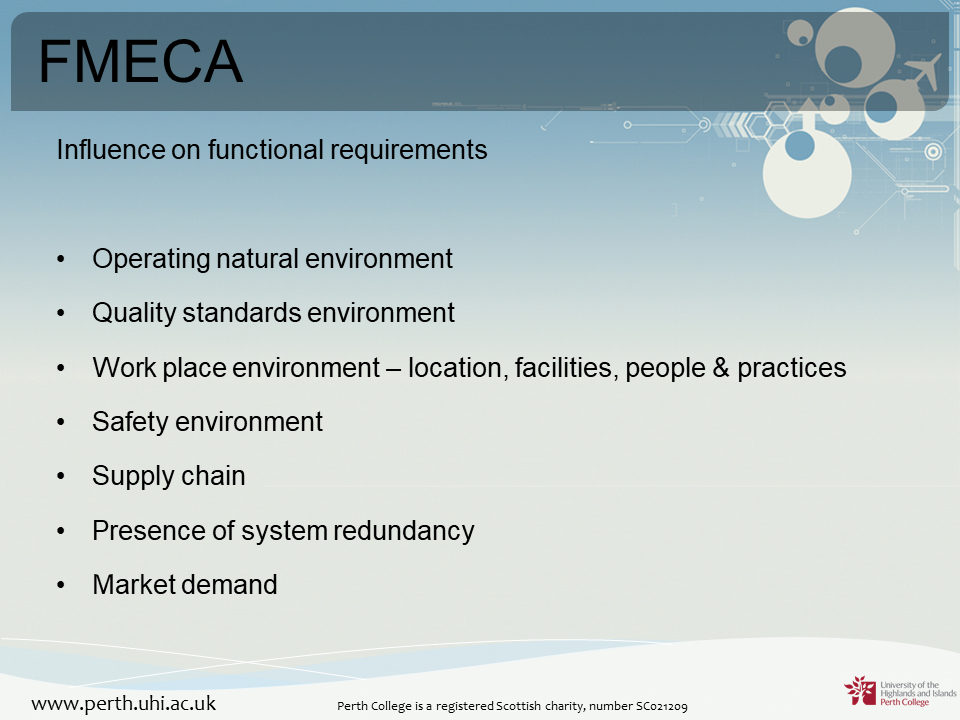
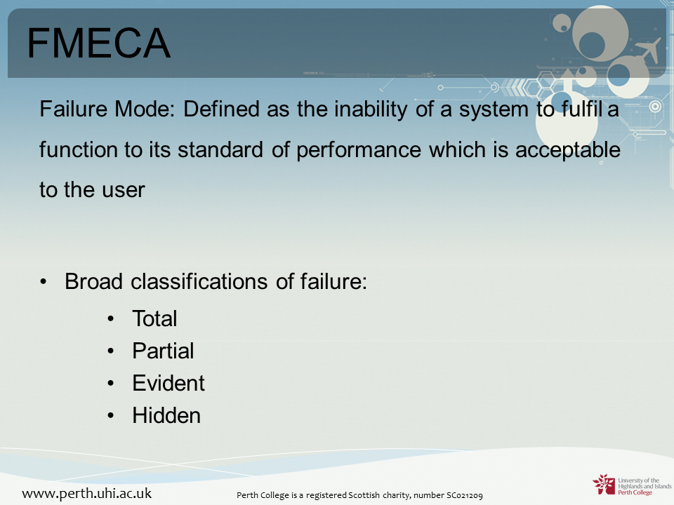
© Calum Aird (Perth College UHI)
Consequence Analysis
Finally, we will very briefly discuss consequence analysis.
As could be predicted from the name, consequence analysis can be defined as:
“…the process of examining the possible effects of a planned activity, or the expected effects of incident outcome cases, independent of frequency or probability.” (ThePD, 2015)
Taking this as our definition, it can be seen that FTA, FMEA and FMECA can all be used as forms of consequence analysis, but the significant difference here is that Consequence Analysis considers both positive and negative outcomes and does not pay attention to frequency.
It is commonly used in high hazard industries where some potential failures, no matter how unlikely, can have devastating outcomes. Examples would include the nuclear and chemical industries.
A good example of an incident in which Consequence analysis should have been carried out but was not is the Bhopal Disaster in 1984. The chance the incident happening was extremely remote, but the consequences were devastating.
The Bhopal incident is examined in the following documentary from National Geographic:
Summary
Over the course of this session we have examined various methods of analysing potential failures in industry. We have also considered their individual strengths and weaknesses and when each of them should be used.

References
Frost, N., 2019. The 737 Max has cost Boeing $9.2 Billion and Counting [online]. Available from https://qz.com/1734220/the-737-max-has-cost-boeing-9-2-billion-and-counting/ (27th February 2020)
Office of Nuclear Regulation (ONR), 2017. Fault Studies [online]. Available from http://www.onr.org.uk/jobs/disciplines/nuclear-safety-inspector-fault-studies.htm (27th February 2020)
ThePD, 2015. Consequence Analysis [online]. Available from https://www.theprojectdefinition.com/consequence-analysis/ (27th February 2020)